The first prototype front plate was in Greek language
#blast_from_the_past
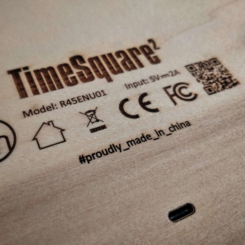
TimeSquare - the first prototype
“Once upon a time, in a kingdom far far away” – that’s how almost every fairytale starts.
For our fairytale, that time was back in 2014 and that “kingdom” was our hometown of Thessaloniki, indeed far far away from where we are now. That’s when and where we initially came up with the idea of time² and built the first prototype. At that time, we were calling it TimeSquare and it was a lot different than it is today.
The housing
We knew it had to be based on wood, but we had absolutely no experience in working with that material at the time. Not only that, but we couldn’t have direct access to a wood working lab and laser cutters where not simple to find at that time and place.
Appearance was the most important aspect of the project and it had to be perfect even on the proof-of-concept stage. The way we saw it, if it didn’t look good, there was no project.
We always loved that contemporary and minimalistic IKEA Lack design, with the strict rectangles and the thick lines, so the initial design was inspired by it. It was easy to follow those principals and design a simple rectangle box to enclose the project and assign its construction to a professional wood workshop. And that’s exactly what we did.
But the biggest challenge was how we were going to carve out the words on the front panel. Initially, misguided by our lack of experience, we were naive enough to think we can do it by ourselves with ordinary tools. We lost countless hours trying to accurately cut plywood using stencils with different wire saws and different bits on a Dremel router. As it should be expected, the results were far from acceptable.
Finally, we found a company that manufactured signs and they owned a laser cutter big enough to fit our 45 x 45 cm front plate. They were nice enough to accept a custom order from us. The result was perfect but, at that time and place, the cost for just cutting our piece of plywood according to our design was higher than the full BOM cost of time² today.
The next task was to create light insulated compartments behind the front plate, one for each word, so that when a word lights up, the light doesn’t also affect the neighboring words. We used slices of plywood for that, and since we didn’t care for the appearance of the internals, we cut them with a jigsaw and installed them using metal 90° angle brackets.
The light
The housing was finished at this point but there was still one issue – with the letters laser cut on the front plate, looking the clock from the front you could see the internals of the housing through the holes. We needed some material to cover those holes and that was a challenge because:
- The material should have a wood like appearance.
- The material should allow most of the light coming from the inner side be visible on the outer side.
- If possible, the material should help diffuse that light so that only the light was visible from the outside and not the light source.
On modern time², we use laser cut acrylic sheet to get these -and a couple of added- properties. But back then, with our limited resources, we decided to go with a double layer of common parchment paper.
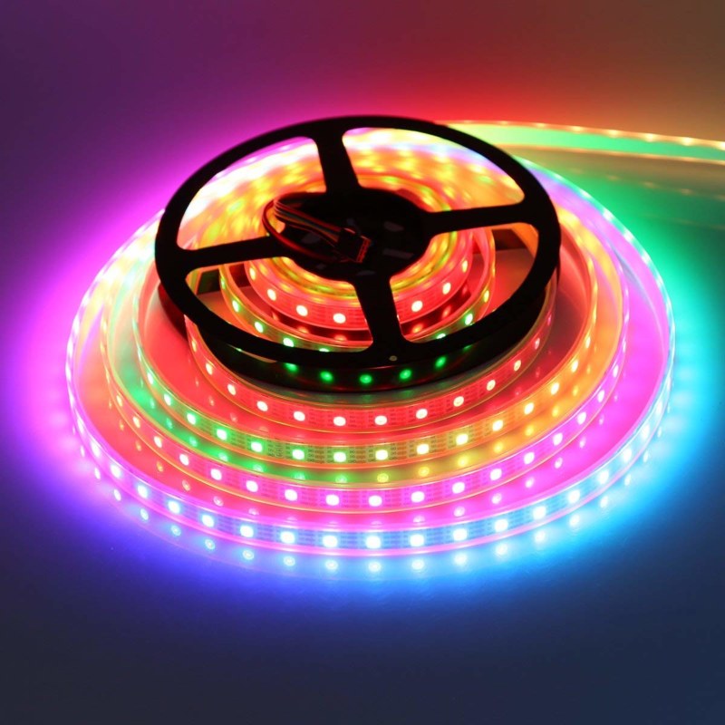
After that, of course we needed a powerful enough light source. Since the word compartments were variable width rectangles, we decided that the best solution was variable length segments of LED strip.
At that time, there were far less options for LED strips than there are today. Individually addressable LEDs were rare and expensive, so we went with conventional cool white 12V 60 LED/m strips. That way, each compartment, depending on its width, was lit by 5 to 10 powerful 5050 LEDs.
The jungle of wires feeding power to the LED strip segments
Testing the control circuit using simple LEDs
The control circuit
There were 23 individual compartments (words) in the prototype, so we needed to individually control 23 LED strip segments. We also wanted smooth transitions from each clock display to the next one, so just switching on and off the strips wouldn’t cut it. We needed to be able to dim each strip segment. That meant that we needed a controller with at least 23 PWM capable GPIO pins.
Our experience at that time was limited to AVR based Arduinos, but even Arduino Mega didn’t have so many PWM capable GPIO pins. So, we had to find a solution.
When GPIO pins are not enough, the standard solution is to employ shift registers on the design. So that’s what we also did. We used 3 8-port shift registers in series. But hardware PWM is not available when someone uses shift registers, so we needed to develop a software solution to control the 23 LED strip segments through shift registers with support for 8-bit resolution dimming.
This solution also limited us to single color LEDs instead of RGB LEDs. Using RGB LED strip segments would mean that the design would be 3 times more complicated. It would need 9 shift registers, 9 Darlington arrays and the wire jungle from the Darlingtons to the strip segments would be 3 times denser.
Following this solution, now we only needed 3 GPIO pins to control all the strip segments. We didn’t need Arduino Mega. Even Arduino Uno was an overkill. We went with the smallest Arduino with USB, the Arduino Nano.
The last challenge was powering the setup. Arduino GPIO pins operate at 5V and can supply a maximum of 20mA. This may be enough to drive a single indication LED but it’s far for being able to power whole strips of 12V super bright LEDs. To solve this, the outputs of each 8-port shift register was connected to an 8-port Darlington array. Arduino Nano can be powered through an embedded voltage regulator that accepts 12V as its input, so we used a 12V power supply to power the Nano and the LEDs through the Darlington arrays.
The clock
Arduinos, at least AVR based ones, cannot keep time. They need an external RTC. Having no prior experience, we used a DS1307 based module. At first, everything seemed fine but soon we discovered that these modules were based on quite inaccurate crystals and lack temperature compensation, resulting on time drifting around 20 seconds per day. After using the prototype for one month, the clock had drifted 10 minutes behind actual time and needed adjustment.
The result
TimeSquare looked great! Whenever someone saw it, they wanted to order one. But the truth was that it was just a proof of concept and far from being a final product:
- There was no printed board. The whole internal circuit was based on 4 mini breadboards.
- The parchment paper solution was very fragile and only used as a cheap & dirty workaround. It could easily be ripped or otherwise damaged.
- The timekeeping function was bad due to the DS1307 module. It would constantly need time adjustment.
- There was actually no way to adjust time besides opening the housing, connecting the Arduino to your computer through USB and configuring a new time through a command on the serial interface. Even then, we were strict about not including any buttons in the setup that would ruin it’s appearance. But that made it completely impractical.
The DS1307 module was one of the initial mistakes
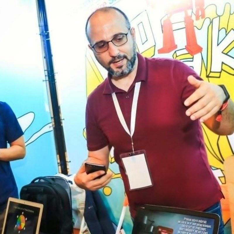
While developing the prototype in our Thessaloniki office in 2014
It's all about the experience
When the proof of concept was finished, the project entered a hiatus period until 2018 when we moved to Shenzhen and development of time² began. So why all this?
We like to make and we like to learn through making. TimeSquare was one of our first projects. It was followed by a period of other creative projects like MagnetLight and TimeWall, each with many design and manufacturing challenges and numerous revisions. The development of time² as a commercial product could not have started without the experience gained from dealing with all these challenges.
It’s a very long way from the concept of the idea and the blueprints to actually making a product. It’s not just making it, but making it reliable and efficient, with a clear and easily reproducible manufacturing procedure without sacrificing design principles for convenience, keeping it serviceable and following product safety standards while optimizing materials and assembly cost.
But it wouldn’t be worthy if it was easy. Would it?
What now?
“Once upon a time, in a kingdom far far away” – that’s how our fairytale started. But how does it end? Well, that’s up to you.
time², the much more advanced successor of TimeSquare, will be soon featured in a crowdfunding platform near you. And with your help, we are sure it will be a successful campaign, and the fairytale will end with all of us “living happily ever after”.
Related Stories
Did you like this story? Go ahead and read some more!

time² | TimeSquare – the first prototype